Harris County Toll Road Authority SH 249
Challenge:
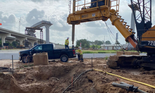
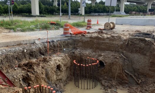
The Harris County Toll Road Authority (HCTRA) project added 4 direct connectors to the existing interchange at SH99 and SH 249. The previous layout of the interchange required vehicles to exit the highway and go through stop lights to get onto an alternate highway, which inevitably caused delays and traffic congestion. The new connectors for the interchange are composed of flyovers which will significantly improve traffic flow in the area. With the construction of the new connectors, there was a need for extensive drilled shaft testing. For quality control, the project specified verification of drilled shaft verticality before concrete pouring and crosshole sonic logging (CSL) after placement of the concrete.
Method:
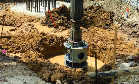
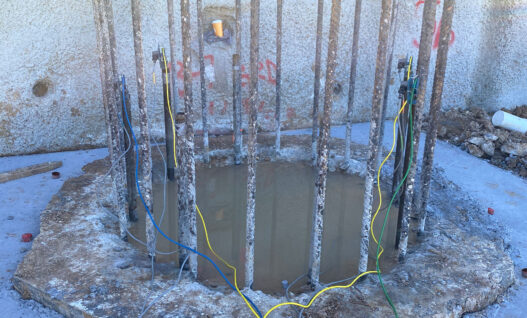
The specifications for this project required the verticality of all drilled shafts be verified. The allowable tolerances for this project were 1 inch of horizontal centroid deviation for every 10 feet of drilled length, or 0.83%. Based on the drilling conditions at this site, as well at the shaft diameters and shaft depths, these shafts required drilling slurry. GRL performed verticality testing with the Shaft Area Profile Evaluator (SHAPE) on approximately 400 drilled shafts. The SHAPE device was able to be quickly deployed via a Kelly bar attachment with results generated typically within 15 minutes of the start of testing. The various drilled shafts ranged in diameter from 36-inch to 96-inch and up to 105 feet in total length. Additionally, all shafts received CSL testing to assess concrete quality around the cage.
Results:
Some shafts encountered verticality exceeding the specified limit. When identified, the contractor then corrected the shaft, and the verticality was tested again. Figure 1, as identified below, displays a profile view of the tested shaft that was not within the specified limit of verticality. Figure 3 shows the top of the shaft and the bottom having a centroid offset of 1.28 ft. After correcting the verticality with a slight increase in the excavation radius, another assessment was made with the SHAPE. This time, the shaft centroid was within the specified limit with an offset of 0.06 ft as can be seen in Figures 2 and 4. Figure 5 shows the results of the crosshole sonic logging. By identifying verticality divergence early in shaft construction, contractors can quickly take action to correct excavations, without hindering project timelines.

Project Details
Client: Williams Brothers Construction Co., Inc.
GRL Office: Texas
GRL Services
- Drilled Shaft Verticality Assessments
- Crosshole Sonic Logging
-
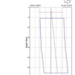
- Figure 1. Maximum Eccentricity Profile, Test 1
-
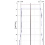
- Figure 2. Maximum Eccentricity Profile, Test 2
-
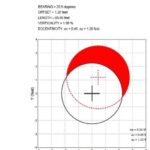
- Figure 3. Maximum Eccentricity Plan View, Test 1
-
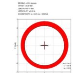
- Figure 4. Maximum Eccentricity Plan View, Test 2
-

- Figure 5. CSL Results