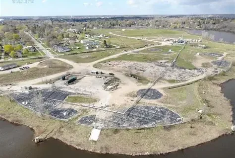


Alligator River Bridge
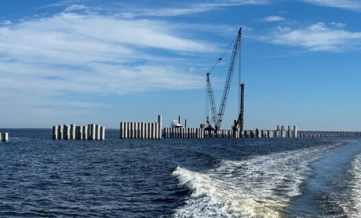
Challenge: The Alligator River Bridge, built in 1960, is a swing-span bridge that allows for boat passage on the Alligator River. Due to recuring mechanical failures and bridge repairs, a new bridge was proposed and designed. The new bridge is 3.28 miles-long with a planned 100-year lifespan. The cost of…
Read More >