North Madison Substation
Challenge:
Perform measurements of accelerations and stresses in non-uniform piles during vibratory driving. Analyze and interpret the data as an aid in the investigation of weld fractures occurring during pile installation.
Method:
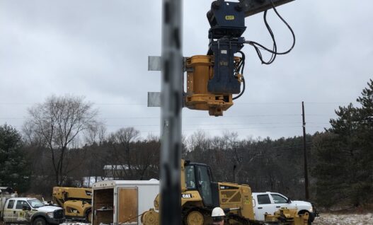
Vibratory Hammer Dynamic Pile Driving: The composite piles consisted of built-up steel members with an overall open cross section. The hammer was a Movax Sonic Grip model with 50 Hz maximum driving frequency at 3000 cycles per minute, with a maximum centrifugal force of 200 kips. To set and correctly align the pile, the vibratory hammer was initially clamped to brackets which were welded to the sides of the pile at approximately one third of the pile length below the top. The pile was initially driven as far as possible with a side-mounted hammer. It then, was top driven with the hammer clamped to brackets welded to a heavy steel plate, which was welded to the pile top.
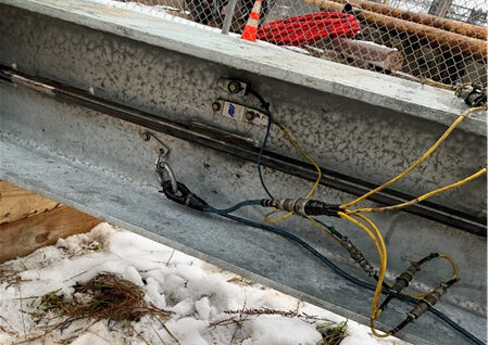
Measurements: One level of instrumentation was located a short distance below the top pile plate; the second one was near the lower attachment brackets. The gages on the lower level of instrumentation were removed when the hammer clamping was switched from side to top brackets. Eight channels of PDA data were available for analysis during the side mounted hammer driving; and four channels of data were analyzed during driving to design depth. Dynamic testing was conducted at both a site where the pile driving was easily administered; and at a second site where refusal occurred. In addition to recording the PDA data, the driving progress was monitored with a video camera.
Analysis: First, the PDA measurement signals of strain and acceleration were analyzed by the PDI-VIB program, which balances the signals, integrates the acceleration to velocity under consideration of the pile penetration speed, and integrates velocity to displacement. Next, the video recordings were analyzed for penetration speed vs. depth.
The strain measurements were converted to force after adding a static component which represented the hammer weight. Given the corrected force records, the PDI-VIB program calculated the peak values of stress, force, soil resistance (at the time of driving) and power transfer. It also generated summary plots and time histories of measured and derived quantities.
Results:
The soil resistance proved to be less important than stresses, acceleration and forces. For that reason, not only averaged strains, stresses and forces, but also the individual signals, were evaluated. For example, given the offset of the strain sensors from the neutral axis, bending stresses were estimated at the bracket attachment points. These bending stresses were highest when the soil resistance was minimal, i.e., when the pile was practically supported only by the vibrating hammer. Also, all processed records were searched for maxima and minima of stresses and accelerations.
Axial stresses typically were less than 5 ksi during hard driving; during easy driving, stresses due to bending could reach almost 6 ksi. Maximum acceleration levels were less than 10 g’s generally. Depending on soil resistance, hammer frequencies varied between 15 and 50 Hz.
Project Details
Client: American Transmission Company, LLC
GRL Office: Pennsylvania
GRL Services
- High Strain Dynamic Testing
- GRLWEAP Analyses
- PDI-VIB Program Data Analysis
-

- Figure 1. Vibratory Driving Record