Offshore Wind Farms in New Jersey
Challenge:
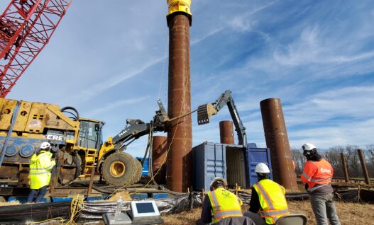
GRL Engineers were brought onto a research project related to offshore wind to provide deep-foundation expertise. The New Jersey coastline has been expanding its offshore wind efforts since the signing of Executive Order 28 from New Jersey Governor Murphy in 2020.
Addressing the potential in South Jersey for wind farms, studies on glauconite soil deposits have been a focal point for various universities. GRL Engineers conducted a driven-pile test program including Wave Equation Analyses utilizing GRLWEAP, dynamic testing utilizing the Pile Driving Analyzer® (PDA) for pile monitoring and CAPWAP® analysis at pertinent depths, as well as a full complement of static load tests utilizing Static Load Tester and ShapeArray. The results from these tests will assist in establishing criteria for future pile installations in glauconite present soils.
Method:
Before driving, soil borings and cone penetrometer soundings were performed for initial assessment, while GRL performed SPT energy calibration during sampling. The water table above the topsoil layer was logged as 3.5 ft (1 m), with soil conditions described as very loose, poorly graded sand, followed by loose to medium dense alluvial deposits containing poorly graded sand and clay. The next layer contained loose to medium dense clayey sand. Around 50 ft (15.2 m) there was a mix of medium dense clayey sand of glauconite sand, followed by dense silty sand.
The pile driving program consisted of driving pipe piles that had Length to Diameter ratios of 72:1 and 12:1. Some pile groups were re-driven after a waiting period. This allowed for comparable results to determine efficient driving criteria. The pipe piles were instrumented with accelerometers and strain transducers to collect dynamic measurements. Signals were analyzed with an 8G PDA. Following driving, PDA results were further assessed using CAPWAP analyses, which provided shaft resistances, end-bearing values, damping factors, and soil quakes.
Along with the dynamic load test program, axial and lateral static load tests were performed. Using test loads indicated by jack pressures, axial rigidities and concrete moduli for strain-gage data reduction were determined using the Incremental Rigidity (I.R.) method for both compressive and tensile tests on the concrete-filled piles. Results from both embedded vibrating-wire sister-bar strain gages and distributed fiber Bragg grating (“FBG”) sensors were evaluated using I.R., and pile deflection shapes were produced for each loading increment utilizing Shape Arrays devices.
Results:
The PDA testing allowed for the assessment and quantifications of time-dependent soil strength changes. It also allowed for unit friction values, and dynamic parameters to be established, which in turn would allow for a more representative Wave Equation model to be simulated. The axial static load testing (compressive and tensile) results were compared with the dynamic load testing results for further assessment of unit friction values vs. depth. The lateral load test (Figure 1.) provided information regarding the pile and soil stiffness response, which is an important consideration for lateral loading conditions when assessing the deflection shape of the pile.


Project Details
GRL Office: Pennsylvania
GRL Services
- SPT Energy Calibration
- High Strain Dynamic Testing
- CAPWAP® Analyses
- GRLWEAP Analyses
- Compressive, and Tensile, Static Load Testing with embedded instrumentation utilizing Static Load Tester
- Lateral Static Load testing with measured deflection shape utilizing ShapeArray
-
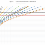
- Figure 1. Lateral Displacement vs Elevation