Harbor River Bridge
Challenge:
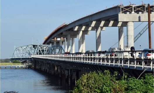
Proposed in 2014, the Harbor Bridge replacement project required quality assurance testing. Harbor Island, is accessed through this drawbridge, located on US-21 in South Carolina. This vacation destination sea island was originally hunting land that had little need for incoming and outgoing traffic, which was sufficient for the bridge’s original capacity. However, the narrow lanes present potential hazards to drivers, the county of Beaufort decided to take action and proposed a new design. The new bridge would consist of 12-foot-wide lanes with 10-foot-wide shoulders, and will reach heights of 65 feet, allowing clearance for shrimp boats and fishing charters without disrupting traffic.
Method & Results:
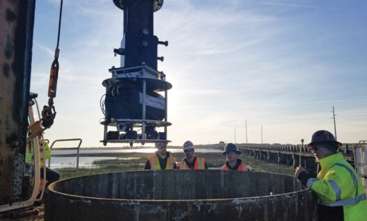
The testing was performed on a sacrificial test shaft as was required by the South Carolina Department of Transportation. GRL used the Shaft Area Profile Evaluator (SHAPE) in the slurry-filled hole for verticality and profile analyses. With a visual representation of the shaft, they were able to assess an offset verticality of 0.22 ft. An evaluation of shaft base cleanliness was performed with the Shaft Quantitative Inspection Device (SQUID). Using penetrometers with embedded strain gages and displacements plates, the resulting force and penetration distance into the bearing material formed a resistance vs displacement plot for real-time quantitative assessment of the debris thickness at the shaft base. The average debris thickness prior to concrete placement was approximately 0.20 inches.
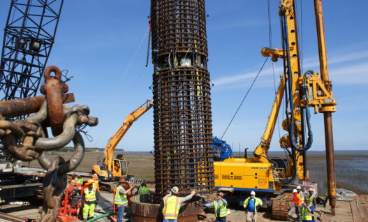
To assess concrete quality and concrete shaft geometry along the instrumented length of the shaft, the engineers performed Thermal Integrity Profiling using Thermal Wire® cables. Eight cables were attached along the reinforcing cage during testing. Prior to concrete placement, the TAP-Edge and TAG (Thermal Acquisition Port data loggers) were connected to the Thermal Wires for on-site data collection via the Cloud. An automatic reading was taken every 15 minutes and sent for remote analysis. Based on the thermal results, the Effective Average Radius was generally consistent with the reported as-built shaft diameter of 96.75 inches from the top of the shaft, to a depth of 62.88 feet and 94 inches from 62.88 to the bottom of the shaft.
Eight days after the shaft construction, GRL Engineers used Bi-Directional Static Load Testing to evaluate load bearing and capacity. The Bi-Directional Static Load Test was conducted using a jack assembly containing three 1,500-kip GRL-Cells. An equivalent top loading (“ETL”) curve was constructed using the load-transfer method. This method indicated that the equivalent maximum top load would be 7,863 kips.

Project Details
Client: United Infrastructure Group, Inc.
GRL Office: Central
GRL Services
- Drilled Shaft Verticality Assessment
- Drilled Shaft Bottom Cleanliness Evaluation
- Thermal Integrity Profiling
- Bi-Directional Static Load Testing