Bi-Directional Static Load Testing (BDSLT)

BDSLT with the GRL-Cell
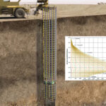
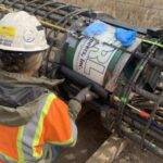
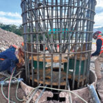
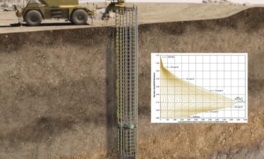
A bi-directional static load test (BDSLT) is a test in which a deep foundation element is internally loaded from a specific location or multiple locations along its embedded length. The load is applied from a jack assembly comprised of one or more GRL-Cells typically affixed between upper and lower bearing plates. The jack simultaneously pushes upward against the shaft resistance above the jack assembly location and downward against the sum of the shaft resistance below the jack assembly and the toe or base resistance. The deep foundation element is instrumented to provide information about shaft and toe movements as well as the soil resistance from the applied load. GRL-Cells can be installed in drilled shafts, augercast piles, drilled displacement piles, slurry wall panels and barrettes.
For an overview of bi-directional static load testing, watch the animation below.
Bi-Directional Static Load Test Benefits include:
-
- High-capacity static load test method for deep foundation elements.
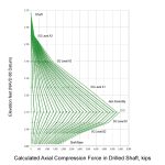
- Separates soil/rock resistance and movement data for shaft and toe.
- Determines magnitude of the mobilized shaft and toe resistances.
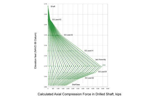
- Embedded strain gages within the foundation element determine the soil/rock resistance distribution along the foundation length for optimizing foundation design.
- Not restricted by structural or geotechnical limit of load frame, reaction beams, or reaction piles.
- Multiple GRL-Cells can be used at a single jack assembly location or at multiple jack assembly locations to apply larger loads.
Bi-Directional Static Load Testing (BDSLT) is standardized by ASTM D8169 – Standard Test Methods for deep foundations under Bi-Directional Static Axial Compressive Load.
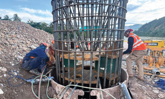
In drilled shafts, configuration of the jack assembly to accommodate the cells as well as tremie pipe or pump line location is important for concrete placement. Generalized plan and elevation views of single and multiple GRL-Cell jack assemblies illustrating this consideration are provided below.
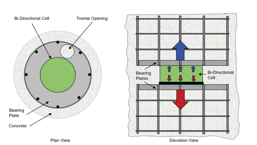
Generalized Plan and Elevation View of Single GRL-Cell Configuration with Offset Tremie Location
Generalized Plan and Elevation View of Multi GRL-Cell Configuration with Center Tremie Location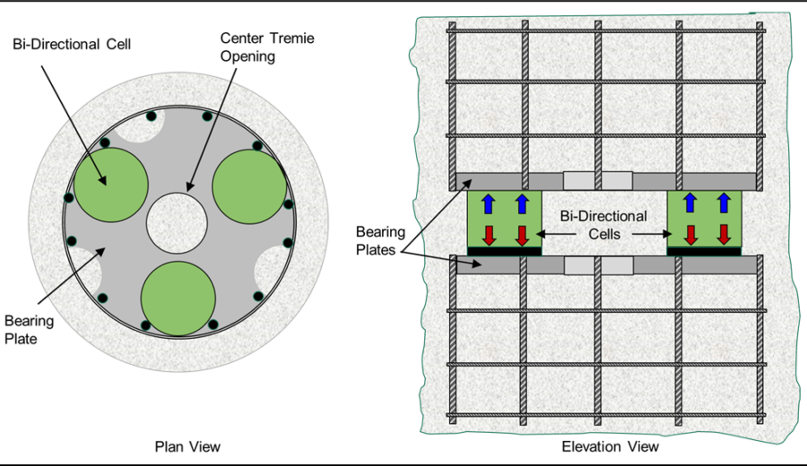
Nominal GRL-Cell sizes are summarized in the following table:
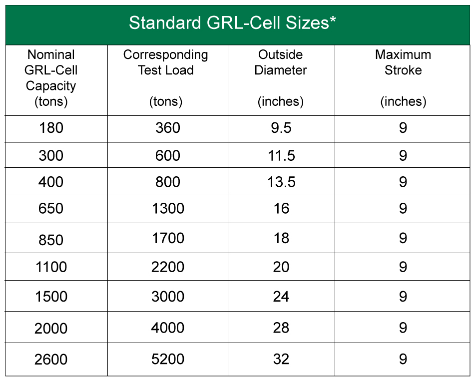
*GRL-Cell capacities based on nominal 10,000 psi +/- operating pressure. Higher cell capacities are available at higher operating pressures. All cell sizes are subject to change.