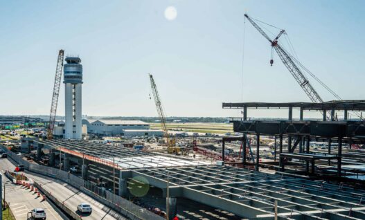
John Glenn International Airport Terminal in Columbus
Challenge:
Work on the John Glenn International Airport’s new Midfield Terminal is part of a major upgrade initiative intended to add a terminal and improve access for the growing Columbus region. News reports describe the effort as a multiyear program valued at nearly two billion dollars with a new million square foot terminal, expanded passenger areas and elevated walkways connecting the terminal to new parking facilities.
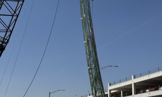
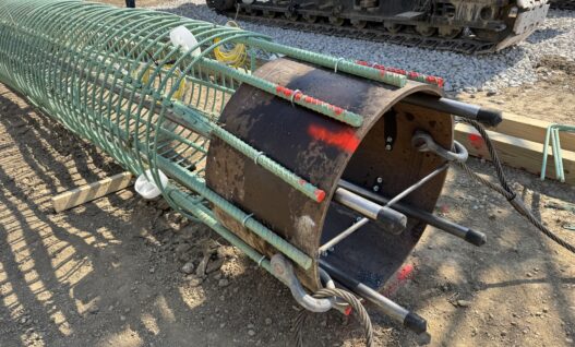
Within this larger program, the Midfield Terminal project includes a new two-story terminal with a mezzanine, an elevated pedestrian bridge over the departure road and a multilevel terminal front bridge. The front bridge is supported by 60-inch and 72-inch drilled shafts at the piers and 14-inch ACIP piles at each abutment. The project was designed to meet LEED sustainability criteria. GRL Engineers was contracted to assess the drilled shafts and ACIP piles integrity, geometry and axial performance. Production testing also included Thermal integrity Profiling (TIP™) on all drilled shafts for the front bridge and test piles for the terminal building, along with Low Strain Integrity Testing (PIT) of more than 225 ACIP piles supporting the terminal building. The entire testing program was accepted by airport representatives.
Method:
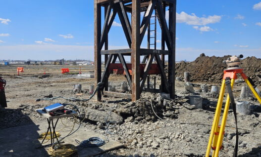
GRL Engineers used a comprehensive foundation evaluation program that included Thermal Integrity Profiling (TIP™), Crosshole Sonic Logging (CSL), Static Compression Testing (SLT), High Strain Dynamic Load Testing (HDSLT), and preplacement geometry and base cleanliness assessments. Demonstration drilled shafts were tested with various test methods to confirm the installation contractor’s means and methods prior to production shaft installation.
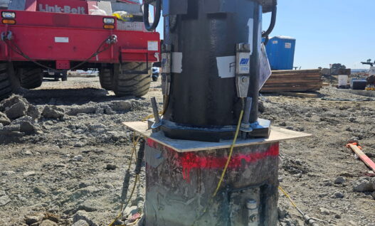
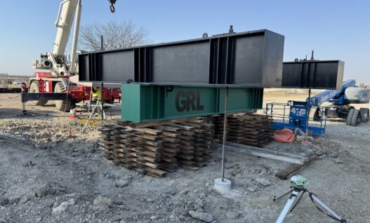
Static compression load testing was performed on ACIP piles at both abutments. High Strain Dynamic Load Testing using the APPLE system and Pile Driving Analyzer® (PDA) instrumentation was carried out on ACIP production piles and on the demonstration drilled shafts. CAPWAP® Analysis was performed to estimate mobilized resistance and the simulated static response of each element.
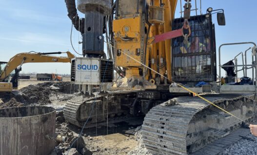
The Shaft Area Profile Evaluator (SHAPE®) and the Shaft Quantitative Inspection Device (SQUID™) were used on several drilled shafts to evaluate excavation geometry, alignment and base cleanliness immediately before concrete placement. PIT testing supported ACIP foundations in the terminal building area and Pile Installation Recorder (PIR-Q) data recorded installation details during pile construction.
Results:
TIP and CSL testing showed uniform material properties within the drilled shafts. TIP testing on the Pier 10 shaft confirmed consistent temperature trends and effective radii that aligned with the design profile (Figure 2). CSL results on the 48-inch demonstration shaft showed consistent arrival times and energy transmission through all tube pairs and test runs with no indications of anomalies.
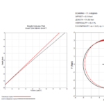
The ACIP abutment piles performed well during static load testing (Figure 1). Both test piles carried the design loads with limited movement. The forward abutment pile sustained loading to about 526 kips before a structural issue developed near the top of the pile. This was not related to geotechnical performance. The rear abutment pile carried about 520 kips during a one-hour hold period without signs of plunging. These findings indicated that both piles had axial capacity well above design requirements.
Dynamic testing supported these observations. CAPWAP analysis of the ACIP production piles produced mobilized capacities between about 360 and about 420 kips. The drilled shaft demonstration elements carried significantly higher loads with the 48-inch shaft mobilizing about 2,310 kips and the 72-inch shaft mobilizing about 2,595 kips. No dynamic test achieved geotechnical failure.
SHAPE and SQUID tests demonstrated acceptable shaft geometry and base conditions. The 72- inch demonstration shaft showed a small offset and near vertical alignment. (Figure 3) Base debris measurements were generally less than one inch. The 48- inch Shaft 42 exhibited uniform excavation characteristics and acceptable alignment with debris readings ranging from about 0.22 to 1.47 inches. Shaft 36 showed a somewhat larger offset but still acceptable base cleanliness. (Figure 4). These evaluations confirmed that the shafts were appropriate for concrete placement at the time of testing.
Together, the integrity testing, geometry assessments, and load testing confirmed that the drilled shafts and ACIP piles met the structural and performance requirements of the project. The results supported foundation acceptance and allowed work on the terminal front bridge to progress as planned.

Project Details
Clients: Beaver Excavating, Richard Goettle, Inc.
GRL Office: Ohio
GRL Services
- Thermal Integrity Profiling (TIP™)
- Low Strain Pile Integrity Testing (PIT)
- Crosshole Sonic Logging (CSL)
- Static Load Testing (SLT)
- High Strain Dynamic Load Testing with APPLE (HSDLT)
- Dynamic Pile Monitoring (PDA)
- CAPWAP® Analysis
-
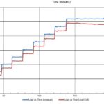
- Figure 1. Compression Load test Results – Fwd Abut Test Pile. Load vs. Time.
-
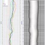
- Figure 2. TIP-R Results – Effective Radius Analysis Tools. Shaft: Pier 10 Shaft 74 at 30h:22m
-
- Figure 4. SQUID Results for Shaft 36. Test number: 1, run number: 8.
-
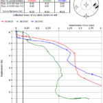
- Figure 4. SQUID Results for Shaft 36. Test number: 1, run number: 8.